UML
•Unified Modeling Language (UML) is a pictogram-based graphical modeling language designed to provide a standardized method for visualizing system design. It is widely used in software development and object-oriented design.
Use
•UML is used to present, visualize, organize and construct documentation required for successful development of object oriented software. UML provides a modeling standard for representing software architecture. The different representative elements are:
•Product/software function
•The actors
•Make
•Database schema
•Software components
•Reusing components
Thanks to UML modeling tools, it is also possible to automatically export all or part of the code of a software application, for example in the Java language, to various generated documents.
Legal Remedies
•UML is divided into several categories:
oObservations: these are observables of the system. They describe the system from a given point of view, which can be organizational, dynamic, temporal, architectural, geographical, logical, etc.; By combining all these concepts, it is possible to describe (or explore) the entire system.
oDiagrams: these are sets of graphic elements. They describe the contents of the mind, which are abstract concepts. They can be part of many ideas.
oElement models: these are the graphical elements of diagrams.
Review
•One way to use UML is to look at various overlapping concepts to work together in the definition of the system:
•Use-case view: this is the description of the model seen by the system actors. It matches the expected needs of each actor (the what and who).
•Logical view: this is an internally visible description of the system. It describes how actors’ needs can be met (which they are).
Implementation view: This view defines the dependencies between modules.
•Process view: this is a temporal and technical view, which uses the concepts of competing processes, stimuli, control, synchronization, etc. to analyze the process.
•Distribution view: a view that describes the geographic position and physical architecture of each element of the system (the where).
•Why not defined in UML.
Diagrams
•The diagrams are hierarchically dependent and complement each other, to allow modeling of the project throughout its life cycle. There are fourteen types of diagram
Structural diagrams or static diagrams
•Class diagram: representation of the classes in the system.
•Object diagram: representation of class instances (objects) used in the system.
•Component diagram: representation of system components from a physical point of view, as they are implemented (files, libraries, databases, etc.) .
•Deployment diagram: representation of hardware elements (computers, peripherals, networks, storage systems, etc.) and how system components are distributed among these hardware elements and interact with each other.
•Package diagram: representation of dependencies between packages (a package is a logical container that allows elements to be grouped and organized in a UML model), that is, between sets of definitions.
•Composite structure diagram: representation in white box form of relationships between components of a class.
•Profile diagram: specialization and customization for a certain domain of the UML reference meta-model.
Character diagrams
•Character diagrams combine:
•Use case diagram: representation of the possibilities of interaction between the system and actors (participants outside the system), that is, all the features that the system must provide.
•State machine diagram: representation in finite state machine form of the behavior of a system or its components.
•Functional Diagram:
• a representation in the form of a distribution or sequence of actions of the characteristics of the system or its components
Use case diagram
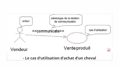
The use case diagram illustrates the use cases shown below
the shape of ovals and the actors in the form of characters. He is showing up
also the communication relations that connect them.
Example: A procurement use case is presented with


.png)
.png)
.png)